Energy storage inverter structure diagram


Contact online >>

Energy storage inverter structure diagram

About Energy storage inverter structure diagram

As the photovoltaic (PV) industry continues to evolve, advancements in Energy storage inverter structure diagram have become critical to optimizing the utilization of renewable energy sources. From innovative battery technologies to intelligent energy management systems, these solutions are transforming the way we store and distribute solar-generated electricity.

6 FAQs about [Energy storage inverter structure diagram]

What type of inverter/charger does the energy storage system use?

The Energy Storage System uses a MultiPlus or Quattro bidirectional inverter/charger as its main component. Note that ESS can only be installed on VE.Bus model Multis and Quattros which feature the 2nd generation microprocessor (26 or 27).

What are the parameters of a battery energy storage system?

Several important parameters describe the behaviors of battery energy storage systems. Capacity [Ah]: The amount of electric charge the system can deliver to the connected load while maintaining acceptable voltage.

What is energy storage system?

Source: Korea Battery Industry Association 2017 “Energy storage system technology and business model”. In this option, the storage system is owned, operated, and maintained by a third-party, which provides specific storage services according to a contractual arrangement.

What are the different types of energy storage systems?

*Mechanical, electrochemical, chemical, electrical, or thermal. Li-ion = lithium-ion, Na–S = sodium–sulfur, Ni–CD = nickel–cadmium, Ni–MH = nickel–metal hydride, SMES=superconducting magnetic energy storage. Source: Korea Battery Industry Association 2017 “Energy storage system technology and business model”.

What is a power electronic based inverter?

In both standalone or grid-connected PV systems, power electronic based inverter is the main component that converts the DC power to AC power, delivering in this way the power to the AC loads or electrical grid.

Can solar string inverters save energy?

A lot of research and development is occurring in power conversion associated with solar string inverters. The aim is towards preserving the energy harvested by increasing the efficiency of power conversion stages and by storing the energy in distributed storage batteries.

Related Contents

List of relevant information about Energy storage inverter structure diagram

Deye Energy Storage Solu ons

This Mode allows hybrid inverter to sell back any excess power produced by the solar panels to the grid. If the " me of use" is ac ve, the ba ery energy also can be sold into grid. The PV energy will be used to power the load and charge the ba ery and then excess energy will flow to grid. Power source priority for the load is as follows:

A typical three-level inverter (a) structure of circuit, and (b

Download scientific diagram | A typical three-level inverter (a) structure of circuit, and (b) three-level inverter space vector diagram for balanced DC-link capacitors [6] from publication: Solar

SINEXCEL PWS2-30K-NA USER MANUAL Pdf Download | ManualsLib

RS-485 is adopted for communication between energy storage inverter and BMS, as shown in the following diagram. Page 49 Communication mode energy storage inverters. This has provided great convenience for detecting and controlling the operation of energy storage inverters. The overall structure diagram for system networking is shown in Fig. 6-4.

International Journal of Electrical Power & Energy Systems

When operating in voltage control mode, the control target of the energy storage inverter is output voltage [8], [9] s overall control structure is shown in Fig. 2.The power loop control takes the active P ref and reactive Q ref as the reference and performs power calculation from the output voltage v C1_a(bc) and output current i L1_a(bc) and adopts the Droop or

SINEXCEL PWS2-30K-NA USER MANUAL Pdf Download

RS-485 is adopted for communication between energy storage inverter and BMS, as shown in the following diagram. Page 55 energy storage inverters. This has provided great convenience for detecting and controlling the operation of energy storage inverters. The overall structure diagram for system networking is shown in Fig. 6-4.

Stability Control of Energy Storage Voltage Source Inverters

Fig. 1. Topological structure of a three-phase inverter. Fig. 2. Block diagram of the state model of an inverter in the synchronous coordinate system. The main circuit topology of a three-phase inverter is shown in Fig. 1. Rg, Lg, Rm, Lm and Cf represent the inverter load-side equivalent resistance and leakage inductance, the

Guide to designing off-grid and hybrid solar systems

Inverter Surge or Peak Power Output. The peak power rating is very important for off-grid systems but not always critical for a hybrid (grid-tie) system. If you plan on powering high-surge appliances such as water pumps, compressors, washing machines and power tools, the inverter must be able to handle the high inductive surge loads, often referred to as LRA or

A Guide to Battery Energy Storage System Components

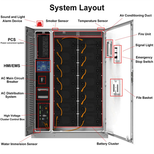
A battery energy storage system (BESS) contains several critical components. This guide will explain what each of those components does. (PCS) or Hybrid Inverter. The battery system within the BESS stores and delivers electricity as Direct Current (DC), while most electrical systems and loads operate on Alternating Current (AC). Due to this

Power Topology Considerations for Solar String Inverters and

This problem has spawned a new type of solar inverter with integrated energy storage. This application report identifies and examines the most popular power topologies used in solar

GRID CONNECTED PV SYSTEMS WITH BATTERY ENERGY

However, in recent years some of the energy storage devices available on the market include other integral components which are required for the energy storage device to operate. The term battery system replaces the term battery to allow for the fact that the battery system could include The energy storage plus other associated components.

Control structure of energy storage grid-connected inverter.

Download scientific diagram | Control structure of energy storage grid-connected inverter. from publication: Linear Active Disturbance Rejection Control for DC Bus Voltage Under Low‐Voltage Ride

10-kW, GaN-Based Single-Phase String Inverter With Battery

This reference design provides an overview into the implementation of a GaN-based single-phase string inverter with bidirectional power conversion system for Battery Energy Storage Systems

Energy storage quasi-Z source photovoltaic grid-connected

Figure 2 illustrates the two operating states of the quasi-Z-source equivalent circuit, where the three-phase inverter bridge can be modeled as a controlled current source. In Fig. 2a, during the shoot-through state, the DC voltage V pn is zero. At this moment, there is no energy transfer between the DC side and the AC side. Capacitor C 2 and the photovoltaic

Solar Energy Application Examples | Semikron Danfoss

Block diagram of a single-phase PV string inverter in 3-level topology Module inverter . A single-phase inverter with low output is connected to each individual solar module. This model is used for sub-arrays with extremely varied orientation and shading, such as on vehicles. String inverter

A Deep Dive into Battery Management System Architecture

Energy Storage Optimization: With the integration of energy storage into various applications, BMS architectures are focusing on optimizing energy storage utilization for better grid stability, energy efficiency, and cost savings. In conclusion, battery management system architecture faces challenges related to cost, complexity, and scalability.

Handbook on Battery Energy Storage System

3.7se of Energy Storage Systems for Peak Shaving U 32 3.8se of Energy Storage Systems for Load Leveling U 33 3.9ogrid on Jeju Island, Republic of Korea Micr 34 4.1rice Outlook for Various Energy Storage Systems and Technologies P 35 4.2 Magnified Photos of Fires in Cells, Cell Strings, Modules, and Energy Storage Systems 40

Simulation test of 50 MW grid-connected "Photovoltaic+Energy storage

The energy storage control strategy is designed for the capacity allocation model, and the capacity allocation model for the PV storage hybrid system has been established. inverter and other collaborative control power generation system. The overall structure of the system is shown as follows. The construction of the system takes into

Inverter-based islanded microgrid: A review on

A review is made on the operation and control system for inverter-based islanded MG. The rest of this paper is organized as follows. Different types of the inverters and the structure with function of an inverter are illustrated in Section 2.Protection is one of the most important and challenging problems for MG systems that it is mentioned in Section 4.

Experimental investigation of a new smart energy management algorithm

The hybrid energy storage system consisting of battery bank and ultra-capacitor unit is investigated. • Integration of 3-phase 4-wire inverter structure to smart grid is experimentally tested. • The hybrid energy storage device has high power density, fast response, and high efficiency is proposed. •

Schematic drawing of a battery energy storage system (BESS),

Download scientific diagram | Schematic drawing of a battery energy storage system (BESS), power system coupling, and grid interface components. from publication: Ageing and Efficiency Aware

Energy Storage Systems

Energy Storage Systems are structured in two main parts. The power conversion system (PCS) handles AC/DC and DC/AC conversion, with energy flowing into the batteries to charge them or being converted from the battery storage into AC power and fed into the grid. Suitable power device solutions depend on the voltages supported and the power flowing.

The Primary Components of an Energy Storage System

It''s important for solar + storage developers to have a general understanding of the physical components that make up an Energy Storage System (ESS). This gives off credibility when dealing with potential end customers to have a technical understanding of the primary function of different components and how they inter-operate

Utility-scale battery energy storage system (BESS)

The BESS is rated at 4 MWh storage energy, which represents a typical front-of-the meter energy storage system; higher power installations are based on a modular architecture, which might

Research on modeling and grid connection stability of large-scale

3. Modeling of key equipment of large-scale clustered lithium-ion battery energy storage power stations. Large-scale clustered energy storage is an energy storage cluster composed of distributed energy storage units, with a power range of several KW to several MW [13].Different types of large-scale energy storage clusters have large differences in parameters

Structure of the NPC five-level inverter | Download Scientific Diagram

The battery energy stored quasi‐Z‐source (BES‐qZS) based photovoltaic (PV) power generation system combines advantages of the qZS inverter and the battery energy storage (BES) system.

International Transactions on Electrical Energy Systems

The distribution generators vary, thus, their microgrid structures. 71, 72 The structure of microgrid consists of the five major: (a) microsources or distributed generators, (b) flexible loads, (c) distributed energy storage devices, (d) control systems, and (e) the point of common coupling components, which are connected to a low-voltage

3. Integration of Solar PV with MPPT Control and Battery Storage

This necessitates essential requirements for solar PV integration with battery energy storage which reduces the fluctuating and unpredictable nature of power extracted from a PV module. The space vector diagram for the NPC inverter of three-phase three-level for DC-link balanced capacitors is shown in controller and control structure

A Full Guide to Photovoltaic Array Design and Installation

The chosen inverter will depend on your solar system''s size and design. If the installation includes a solar battery for energy storage, it should be connected to the inverter or charge controller. This allows for energy storage during peak sunlight hours and distribution when solar production is low or unavailable. Commissioning and Testing

The Architecture of Battery Energy Storage Systems

An Energy Storage System (ESS) is a specific type of power system that integrates a power grid connection with a Victron Inverter/Charger, GX device and battery system. It stores solar

Overall control structure of grid-side inverter of energy storage

Download scientific diagram | Overall control structure of grid-side inverter of energy storage system. from publication: Linear Active Disturbance Rejection Control for DC Bus Voltage Under Low

Superconducting Magnetic Energy Storage: Status and

alternatives. For an energy storage device, two quantities are important: the energy and the power. The energy is given by the product of the mean power and the discharging time. The diagrams, which compare different energy storage systems, generally plot the discharging time versus power. These two quantities depend on the application.

Contact Integrated Localized Bess Provider

Enter your inquiry details, We will reply you in 24 hours.